A
C
E
B
D
F
N
G
P
A
D
B
E
C
H
K
L
M
R
O
S
P
T
V
W
G
A
F
B
C
H
J
X
M
R
N
T
Q
U
W
d
m
s
A ± 0,025 ± 0,005 ± 0,025
C ± 0,025 ± 0,013 ± 0,025
E ± 0,025 ± 0,025 ± 0,025
F ± 0,013 ± 0,005 ± 0,025
G ± 0,025 ± 0,025 ± 0,05-0,13
H ± 0,013 ± 0,013 ± 0,025
J1 ± 0,05-0,15
2
± 0,005 ± 0,025
K1 ± 0,05-0,15
2
± 0,013 ± 0,025
L1 ± 0,05-0,15
2
± 0,025 ± 0,025
M ± 0,05-0,15
2
± 0,02-0,08
2
± 0,05-0,13
N ± 0,05-0,15
2
± 0,02-0,08
2
± 0,025
U ± 0,08-0,15
2
± 0,13-0,38
2
± 0,13
1
2
3
4
85°
82°
80°
55°
75°
55°
35°
80°
86°
3°
5°
β
β
β
β
β
β
β
β
= 70-90°
β
= 70-90°
β
= 70-90°
β
= 70-90°
β
= 40-60°
β
= 40-60°
β
= 40-60°
7°
20°
25°
T m
d
D
V
d m
s
d
C
S
m
30°
0°
11°
15°
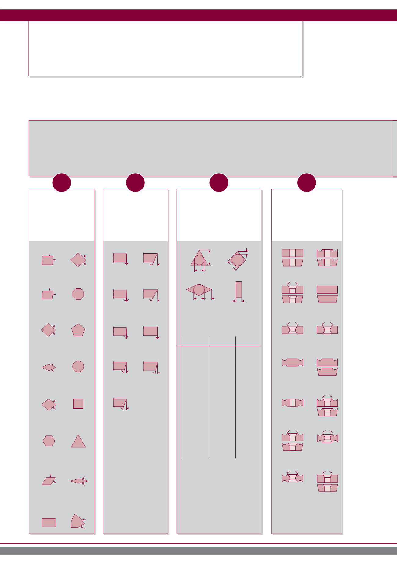
IDENTIFICATION CODE ACCORDING ISO 1832
INDEXABLE INSERTS
R D H X
Shape
Clearence angle
Tolerances
Symbols for fixing
and chipbreakers
Example of identification code according to DIN ISO 1832
O for other clearence angles
that require a more precise
descreption
1
inserts with ground wiper edges
2
depending on size of inserts (see
ISO-Norm 1832)
dimensions or characteristics
requiring precise discreptions
Identification code according ISO 1832
210


